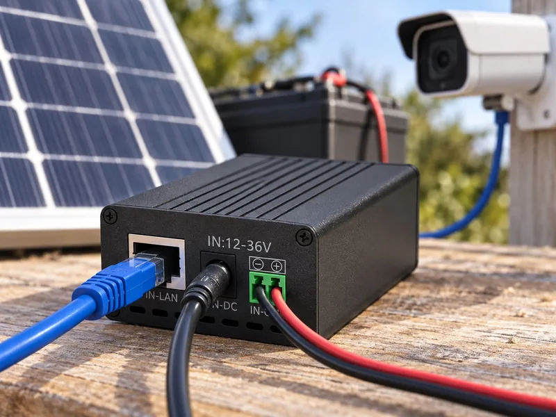
Power Outdoor PoE Cameras Without Grid Electricity
Learn how to size solar, batteries and DC conversion for outdoor PoE cameras, then verify PoE compatibility, cable loss, monitoring and safe restarts.
By Maxsol Team

Outdoor PoE cameras can operate without grid electricity when a solar array, charge controller and battery are sized for the site’s worst operating period—not merely its average summer conditions. The battery supplies a regulated DC path to suitable PoE source equipment, while Ethernet carries data between the camera and its local or remote backhaul.
Two separate checks are essential. First, confirm that the solar and battery system can deliver enough watt-hours through nights, poor weather and equipment restarts. Second, verify that the PoE output is electrically and logically compatible with the camera. An adjustable voltage output alone does not establish IEEE PoE compliance.
Map the solar energy and Ethernet data paths
Treat power and data as two related but distinct paths. This makes faults easier to diagnose and prevents assumptions such as “the camera has a link, so its power supply must be correct”.
Solar energy path
A typical single-site energy path is:
- Solar panel: converts available sunlight into DC electricity.
- MPPT charge controller: regulates charging and matches the panel’s operating conditions to the battery system.
- Battery: stores energy for darkness, cloud and short periods of low solar yield.
- DC protection and distribution: provides suitable fusing, isolation and correctly sized conductors.
- DC converter, PoE injector or PoE switch: converts the battery-side voltage into the voltage required at the Ethernet power interface.
- Outdoor Ethernet cable: carries power to the camera, with some voltage and power lost along the cable.
- Camera: consumes power for imaging, processing, infrared illumination, heaters, motors and other functions.
The panel voltage range, MPPT input limit, battery chemistry, charge profile and low-voltage protection must all be compatible. A nominal “12V” battery system does not remain at exactly 12V throughout charging and discharge, so downstream equipment must tolerate the battery’s real operating range.
For a broader look at these building blocks, see the guide to solar-powered PoE and off-grid networking.
Ethernet data path
A common data path is:
Camera → powered Ethernet link → injector or switch → local recorder, router or wireless backhaul
The direction of application data does not determine the direction of power delivery. The camera is normally the powered device, while the injector or PoE switch acts as the power source.
Depending on the site, the backhaul might be:
- a point-to-point wireless bridge;
- a local Wi-Fi or CPE connection;
- a mobile router;
- a fibre or copper uplink to another cabinet;
- an on-site network video recorder;
- local storage with periodic remote access.
Draw both paths before selecting equipment. Mark every load on the energy diagram, including the router, radio, switch, controller and environmental equipment—not just the camera.
| Architecture element | Power question | Data question |
|---|---|---|
| Solar panel | Can it replace daily consumption in the design month? | None |
| MPPT controller | Does it support the panel, battery and charging profile? | Is monitoring available if required? |
| Battery | Is usable energy sufficient for night operation and autonomy? | None |
| DC converter or PoE source | Can it accept the full battery voltage range and supply the load? | Does it support the required Ethernet speed and PoE method? |
| Ethernet cable | What is the voltage drop at maximum current? | Does length and cable quality support the intended link rate? |
| Camera | What are its maximum and startup demands? | What interface, addressing and backhaul bandwidth does it need? |
| Backhaul | What is its continuous and startup consumption? | Is signal strength, capacity and resilience adequate? |
Measure camera and auxiliary power demand
Do not size an off-grid system from the camera’s typical daytime wattage. Use maximum documented figures where available, then confirm them by measurement under representative operating conditions.
A camera may draw more power when:
- infrared LEDs switch on;
- a heater or demister operates;
- a pan-tilt-zoom mechanism moves;
- edge analytics or recording activity increases;
- a memory card starts or writes heavily;
- the device boots after an outage;
- illumination, microphones or other accessories are enabled.
Record each load in watts and its daily operating time. For variable loads, separate day and night periods:
Daily energy in Wh = watts × operating hours
For example, an illustrative camera drawing 12W for 12 daylight hours and 18W for 12 night hours would consume:
- Day: 12W × 12h = 144Wh
- Night: 18W × 12h = 216Wh
- Camera total: 360Wh per day
A 6W backhaul radio operating continuously would add another 144Wh per day. Conversion losses, controller consumption and any other always-on devices must then be included.
These figures are only an example. Actual camera modes, seasonal night length and equipment consumption must be measured or obtained from the relevant manufacturers.
Include every auxiliary load
A small continuous load can have a large daily effect. Include:
- wireless bridges and CPE units;
- mobile routers and modems;
- Ethernet switches;
- DC converters and PoE injectors;
- charge-controller self-consumption;
- thermostatic heaters or fans;
- environmental sensors;
- relays, timers and remote-reset devices;
- local storage or recording equipment.
Where possible, measure DC input power over a full day-night transition. A brief daytime reading will miss infrared activation and may not capture automatic heating.
Allow for conversion and cable losses
If a converter is described as having a maximum efficiency, do not use that maximum as a guaranteed planning value. Efficiency changes with input voltage, output voltage and load.
Calculate the required battery-side power as:
Battery-side power = PoE load ÷ assumed conversion efficiency
Cable loss also rises with current. In simple terms:
- Voltage drop = current × loop resistance
- Cable power loss = current² × loop resistance
Use the actual cable type, conductor size, route length, termination method and powered-pair arrangement. Copper-clad aluminium cable can produce substantially different results from correctly specified solid-copper cable and should not be treated as equivalent.
Size storage and array for the design month
In the UK, an off-grid camera system should normally be designed around the month with the poorest combination of solar resource, long nights and environmental load—not the annual average. Site-specific shading, panel orientation, tilt and local horizon conditions can matter as much as the nominal panel rating.
Calculate usable battery capacity
Start with the site’s daily energy requirement, required autonomy and permitted depth of discharge:
Required nominal battery energy = daily load × autonomy days ÷ usable battery fraction ÷ downstream efficiency
Suppose a measured system consumes 564Wh per day. If the design requires two days of autonomy, permits 80% of nominal battery capacity to be used, and assumes 90% downstream delivery efficiency:
564Wh × 2 ÷ 0.80 ÷ 0.90 = 1,567Wh nominal battery energy
This is an illustrative calculation, not a recommended universal size. Change every input to match the actual equipment, temperature range, battery limits and service objective.
Also check:
- battery current during maximum load and startup;
- battery-management-system current limits;
- low-temperature charging restrictions;
- capacity variation with temperature and age;
- reserve needed for safe shutdown and communications;
- recovery behaviour after low-voltage disconnection.
A battery’s nameplate watt-hours are not all necessarily available to the load. The battery-management system, charge controller and system settings may reserve part of that capacity or disconnect the output before it is fully discharged.
The Maxsol CS12060 solar power system documents a 120W monocrystalline panel, a 12.8V 60Ah LiFePO4 battery with 768Wh of nominal stored energy, an MPPT controller and three DC12V outputs. Those figures can be compared with a calculated load, but they do not establish a universal runtime or guarantee continuous operation at a particular site.
For a fuller calculation process, including autonomy and seasonal inputs, use this guide to sizing an off-grid solar power system for CCTV.
Calculate the solar array
A preliminary array calculation is:
Required panel wattage = daily energy ÷ design-month peak-sun-hours ÷ system derating factor
The derating factor should account for real-world losses such as temperature effects, controller and wiring losses, panel mismatch, dirt, imperfect orientation and battery charging efficiency.
For example, if an assessment uses:
- 564Wh daily consumption;
- 1.5 peak-sun-hours as a hypothetical design-month input;
- a 0.70 overall derating factor;
then the preliminary array requirement would be:
564Wh ÷ 1.5h ÷ 0.70 = 537W
The 1.5-hour figure is an example calculation input, not a general value for every UK location. Use credible irradiance data for the exact site, panel orientation and design month.
Array sizing must satisfy two competing requirements:
- enough generation to replace normal daily consumption; and
- enough surplus to recharge the battery after an autonomy event.
A system that just balances an average day may take too long to recover after several overcast days.
Verify converter voltage, polarity, pinout and protocol
PoE compatibility is more than matching a wattage figure. Before connecting the camera, verify all of the following:
- Converter input range: it must tolerate the battery’s lowest and highest operating voltages.
- Output voltage: it must fall within the camera’s permitted PoE or passive-power input range.
- Polarity: positive and negative conductors must be assigned correctly.
- Pinout and powered pairs: the source and camera must use compatible pair assignments.
- Power protocol: determine whether the camera expects IEEE 802.3af, 802.3at, 802.3bt or a specified passive PoE arrangement.
- Continuous power: the source must support the camera’s sustained maximum demand.
- Startup demand: it must tolerate boot, infrared, heater and motor inrush without collapsing or resetting.
- Ethernet speed: the converter or injector must pass the required data rate.
- Cable-end voltage: sufficient voltage and power must remain at the camera after cable loss.
IEEE PoE normally involves powered-device detection and, depending on the standard and power level, classification or negotiation. A passive injector may place voltage directly on selected conductors without first confirming that the connected device can accept it.
Therefore, never assume that an adjustable 48V output is automatically equivalent to an IEEE-compliant PoE port.
The Maxsol POE24V adjustable DC-to-PoE converter accepts 12–36V DC and provides an adjustable 12–57V PoE output, Gigabit Ethernet and an LCD voltage display. Its documented continuous load for 12V-to-48V conversion is no more than 30W, while its stated efficiency of up to 94% is a maximum rather than a guaranteed design value.
Those facts do not establish IEEE powered-device detection or negotiation. Confirm the camera’s required voltage, polarity, pinout, protocol, maximum demand and cable loss before connection. Set and test the output with the camera disconnected.
The CS12060 and POE24V can illustrate stages in an off-grid architecture, but they should not be treated as a validated compatible bundle. Compatibility depends on the complete electrical design and the connected equipment.
Include backhaul, monitoring and restart loads
A remote camera is only useful if its data can be stored or transmitted. Backhaul equipment can also represent a significant share of the daily energy budget.
Design the backhaul as part of the system
For a wireless link, confirm:
- line of sight and Fresnel-zone clearance;
- radio link margin through seasonal conditions;
- mounting stability and antenna alignment;
- required throughput for the camera’s configured bitrate;
- continuous and peak power consumption;
- behaviour after router or link failure;
- whether remote configuration remains available during degraded service.
For mobile backhaul, assess local coverage at the final antenna position and account for modem reconnect activity. A router that repeatedly searches for service may consume differently from one maintaining a stable connection.
Monitoring should ideally expose the conditions needed to distinguish power failure from network failure. Useful information can include:
- battery voltage or state information;
- solar charging state;
- load or output status;
- converter output voltage;
- camera reachability;
- router or radio uptime;
- low-voltage and restart events.
Do not rely on battery voltage alone as a precise state-of-charge measurement, particularly while the battery is charging or under load.
Prevent unstable restart loops
After deep discharge, weak solar input may raise the battery voltage enough to restart equipment, only for the startup load to pull it down again. This creates a repeated boot-and-shutdown loop that wastes energy and can interrupt recording or communications.
A safer restart strategy may include:
- a defined low-voltage disconnect threshold;
- sufficient hysteresis between disconnect and reconnect voltages;
- a time delay before restoring loads;
- staged startup of networking and camera equipment;
- priority for monitoring or backhaul where appropriate;
- a minimum battery recovery level before reconnecting the full load.
The correct sequence depends on the site. In some systems, the router should start before the camera so remote monitoring becomes available. In others, local recording may have priority over the backhaul.
Test what happens after complete battery isolation, controller restart and restoration of sunlight. Equipment that starts correctly during a manual power cycle may behave differently when supply voltage rises slowly.
Bench-test and commission before remote deployment
Assemble and test the complete power and data chain before taking it to a difficult site. Bench testing should use the intended cable length and actual camera configuration, not just short patch leads.
A practical commissioning sequence is:
- Inspect ratings and wiring. Confirm panel, controller, battery, fuse, conductor, converter and camera requirements.
- Check polarity with a meter. Do not rely solely on connector shape or wire colour.
- Set the PoE output without the camera attached. Verify the unloaded voltage and expected pinout.
- Connect a suitable test load where possible. Confirm that output voltage remains stable under expected demand.
- Attach the actual cable run. Measure voltage and power at both ends under maximum load.
- Test camera modes. Trigger night vision, heaters, PTZ movement, recording and analytics as applicable.
- Start all equipment together. Observe battery-side current and voltage during simultaneous boot.
- Simulate low battery. Confirm orderly disconnection and stable recovery without rapid cycling.
- Interrupt the backhaul. Check reconnection, local recording and remote-management behaviour.
- Run an extended test. Capture at least a representative day-night transition and review energy use.
- Record configuration values. Document converter voltage, controller settings, fuse ratings, cable lengths and network addresses.
- Label and photograph the installation. Clear records simplify maintenance and reduce the risk of incorrect replacement settings.
Before final commissioning, also verify enclosure suitability, cable-gland sealing, drip loops, condensation control, equipment spacing, surge protection and earthing arrangements. Follow equipment manufacturers’ instructions and use competent installers for the relevant electrical and structural work.
Common design mistakes to avoid
- Sizing from camera wattage while ignoring the backhaul and conversion losses.
- Using annual-average sunlight instead of the poorest design month.
- Treating nominal battery energy as fully usable energy.
- Assuming a 120W panel delivers 120W continuously.
- Using a converter’s maximum efficiency in every calculation.
- Assuming adjustable voltage means IEEE PoE compatibility.
- Checking voltage but not polarity or powered-pair pinout.
- Testing with a short patch lead instead of the planned outdoor cable.
- Ignoring infrared, heater, PTZ and simultaneous startup demand.
- Reconnecting loads as soon as battery voltage briefly recovers.
- Deploying without a way to distinguish power, camera and backhaul faults.
The final design should pass both an energy-capacity test and a PoE compatibility test. Passing one does not compensate for failing the other.
As a next step, compare the linked Maxsol examples with your required port count, measured load, cable and backhaul distance, DC power range, outdoor environment and management needs. Confirm every interface and rating independently before specifying the complete system.